The Situation
I had a two-birds-one-stone situation. The first bird was this: some of the graphics in VIA’s training manuals were in need of a re-do. They were rife with anachronisms. The second bird was that we needed more content for web and social.
The stone that I developed was a series of topical one-page graphic explainer documents. They serve as reference materials in trainings and work great on the web. They introduce complex concepts about MES and VIA’s software by combining exposition with graphical depictions of manufacturing processes. The graphics animate both the processes and system interactions described in the copy. The graphics also enable readers to leverage their spatial memory to map out systems.
Three examples are below.
Man-IT™ System Overview
The document below describes the system components of VIA’s flagship software, Man-IT™. The doc serves as a reference to trainees who are learning the interactions of the systems; it also works as a primer for execs or IT specialists who want to learn how VIA’s software could fit into their manufacturing technology scheme.
Color coordination was key to conceptually dividing the sub-systems. At bottom, a cartoonish representation of a factory assembly line accompanies a list of possible MES applications from the beginning of a manufacturing cycle to its end. The graphic illustrates the production of a gear using manual and automated systems, as suggested by the barcode scanners and assembly machinery. The graphic is complex, but the copy explains the systems at a high level of abstraction. The document is like a map: perfect for trainees who may need reminding as to the interactions of the components. Simple arrows and lines are enough to indicate relationships; in the training guides, it takes paragraphs to explain in writing what the graphic’s arrows do. The graphic assumes a moderate level of familiarity with manufacturing technologies, techinques, and abbreviations.

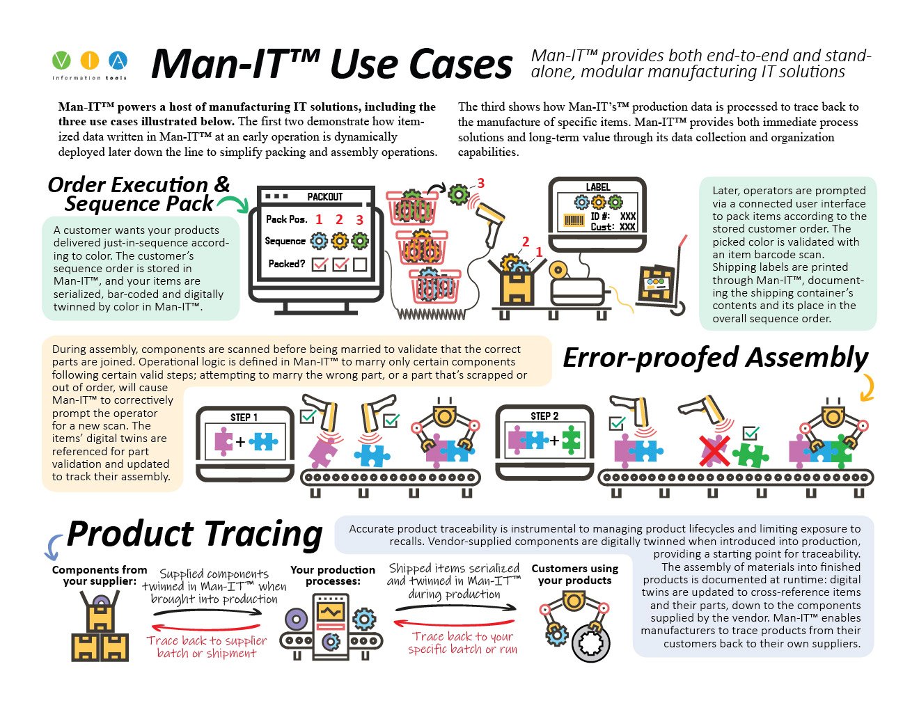
Use Cases
VIA’s Man-IT™ software has many manufacturing applications, but those listed in the document below are typical of VIA’s customers. The use cases also allow process engineers and programmers to get the gist of the software, and to imagine how an MES might fit into their own facilities. Graphic representations of the manufacturing operations visually complement the exposition. Using gears or puzzle pieces as widgets proved useful in animating the processes. The copy is tight but sufficiently explanatory.
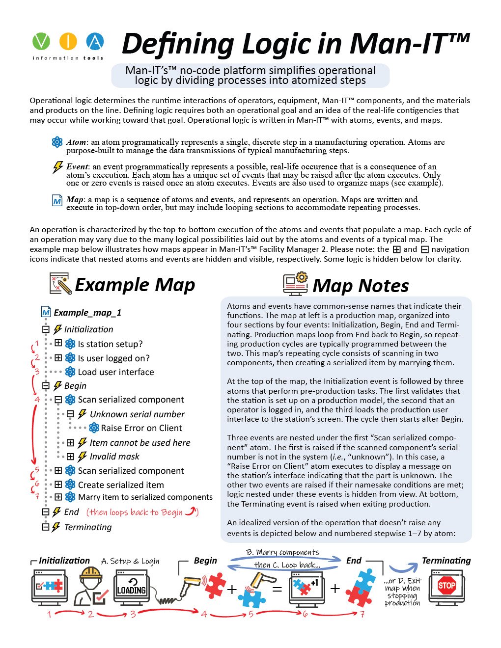
Defining Logic
The content below provides an introduction to defining manufacturing processes with atoms. The doc explains how to design a process in Man-IT™ wherein two parts are married to create a new serialized part. The document accurately depicts the software’s appearance. The exposition underscores the complexity of the interplay between two of Man-IT’s™ programming concepts: atoms and events. I thought it was critical to show the granular level of programming that is required in Man-IT™ by choosing a simple process to examine. It takes a fair bit of programming to get a simple process off the ground. The upshot is that the software can handle very complex process designs for sophisticated manufacturers.